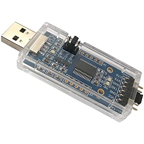
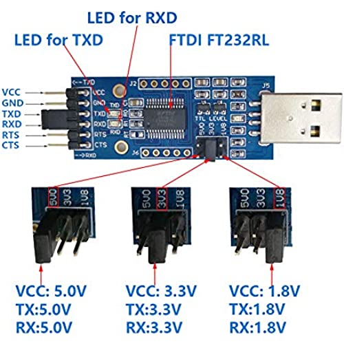
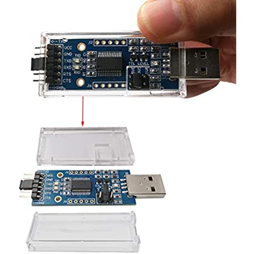
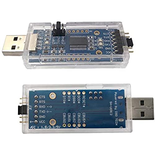
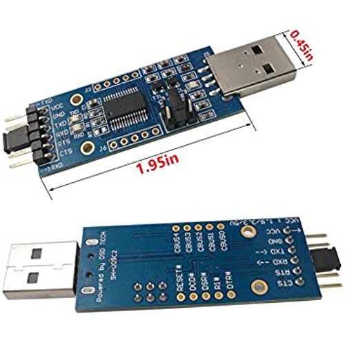
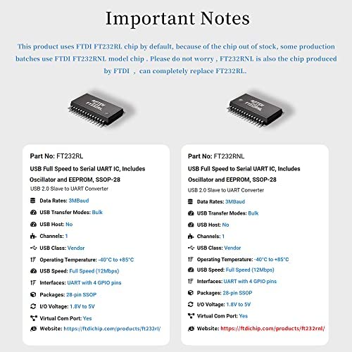


DSD TECH SH-U09C2 USB to TTL Adapter Built-in FTDI FT232RL IC for Debugging and Programming
-

IsPrimeWorthIt
> 3 dayPicked this up for the adjustable voltage settings as my old one only supported 5v. I used this to flash Tasmota onto a Sonoff S31(ESP8266) and it worked perfectly. It is compatible with Linux and worked as-is without installing new drivers.
-

Mondo
> 3 dayWasted hours trying to use an arduino to flash tosmota on a Sonoff device (had worked before), this worked the first time. The device appears well made and it worked immediately, also no drivers required for Windows 10.
-

Samuel T Wilson
> 3 dayAt first it didnt recognize the port I used to plug it in. I solved it by moving to another port. Once I got that corrected, it worked as advertised.
-

Ferne Paucek
> 3 dayWorks great, very well made For those of you looking to program an arduino with this you MUST have a bootloader installed first to use this as a programmer
-

John L.
Greater than one weekI like the multi TTL levels as I have many 1.8, 3.3 and 5V devices and I can use this one adapter on them all. I also got a USB A female to Micro female so I could keep the TTL lines as short as possible.
-

E. Parker
> 3 dayIts a cheap, well made FTDI programmer that can do 1.8v logic. Im not sure what else to say, if you need something that does that thing, get this thing.
-

Watertime
> 3 dayWorks great. Both 5v and 3.3V
-

David
> 3 dayDoes 1.8-5v, flow control as well as and is quite handy if you have to deal with rs232/UART often, or even occasionally. True FTDI chipset, no driver issues, just plug it in, and it works. Highly recommend to anyone in need of such a tool :)
-

ASM
Greater than one weekIm an embedded software engineer, reverse engineer, remaker and Voider of Warranties. Theres a 95% chance that any electronic device I obtain will be subjected to a teardown, a full gallery of explicit high resolution images taken of every nook, cranny and IC marking and datasheets obtained for as many components as possible. Thanks to the ubiquitous UARTs found in many embedded systems, from cameras to routers to electronic cigarette rolling machines (seriously. Its even got silkscreen labels!), thats often my first point of attack when I see a likely UART connection. The first step is determining the logic voltage levels used by that particular uart since 1.8V, 3.3V and 5V are all common(3.3V being most common) and its not a great idea to mix voltages when connecting to a devices I/Os so you want to be sure your USB UART adapter is using the same voltage as the UART. I used to either remove the USB uart adapter when I was done torturing a device or modify the device case to make the USB connector accessible and permanently install the USB adapter inside the case. The problem with that is that most of these adapters have a USB A male connector which means I either have to desolder it and replace it with USB B micro or mini so I can plug a regular device cable in when needed, or I have to use a USB extension cable which I dont tend to have many of and those I do have are either in use or are hiding with my missing left socks and sanity. So instead I started installing stereo headphone jacks so that the 3 conductors of a standard stereo plug can be used to carry GND, TXD and RXD. Those jacks are easy to install using just a drill and pliers, are reasonably cheap while providing a simple, unobtrusive and stable serial port. I only had to make a stereo headphone plug adapter that plugs into the GND, TXD and RXD pins on the USB adapter and set the logic level jumper to the correct voltage for that devices uart (I write it on a label next to the headphone jack on the device case since Ill never remember what device is what voltage). The only caveat is that you only want to insert or remove the headphone plug when no power is being applied to either the device or the USB adapter. This is because when youre inserting the plug, the different sections of the plug, each of which corresponds to one of the UART lines, can make contact with one or more of the contacts inside the jack until the plug is fully inserted. If youve ever plugged headphones or speakers into a live audio jack and heard a buzzy sounds until it was fully inserted, thats the same concept except with signals that can handle being shorted, at least for a short time. UARTs arent generally that resilient to such abuse so always disconnect the USB adapter from your computer and disconnect power from your target device before you insert or remove the serial jack. Then double-check that your USB adapter is set to the right voltage and you can plug that in to your PC and power up the target device. There are plenty of USB adapters that have 1 fixed logic level, often 3.3V. Theres nothing wrong with them other than being useless for other logic level UARTs. I have over a dozen different USB uart adapters with different chipsets, different logic levels and different connector types (and pinouts) for connecting to a target device. Most of them are 3.3V cheapo boards I got from China in bulk and probably arent even legit chips. More than 1 of them has died suddenly, started behaving erratically or in 1 extreme case had an internal short in the IC that popcorned the packaging and blew the fuse on my USB port(luckily it was just a hub). Thats why I decided it was time to standardize my serial ports and use only high quality USB adapters that can be configured for any of the 3 common logic levels as needed. If I had gone with a 4 conductor 3.5mm jack and plug, I could have added a wire for the Vio logic level from the device and had the plug route that conductor to the Vref reference voltage that the USB adapter uses for determining the logic levels to use. Instead I just use this USB adapter which has a 1.8V and a 3.3V voltage regulator to generate those reference voltage from the 5V USB power. Setting the jumpers just connects the output of the corresponding vreg to the FTDI chips Vref input. This is actually the ideal way to do it since the vregs should produce an accurate, stable reference voltage which might not be the case if it came from the device. Anyway, I couldnt ask for a better solution than the one this product provides. Not only is it well made with quality components and a solid design but it also exposes the additional pins of the FTDI chip such as those for hardware flow control and the user-configurable GPIO pins (theyre just unpopulated through-holes but easy to solder on some pins). Even the packaging is very high quality and professional. A++ for DSD Tech!
-

Snoopy Z
> 3 dayWorks well right out of the box. No issue for Arduino on MacBook Pro to detect the serial port and communicate with the target board. A connector is provided for simple loop-back tests to verify everything works fine. Make sure to connect GND to the target board, otherwise the link is not stable. Dont waste time and money to try other USB-serial adaptors. This one works!
